So, what's a Python Drive? you ask. Well it's a Constant Velocity Joint, actually two Constant Velocity Joints (part F & part I) attached to each other by an Intermediate Shaft (part G) that are in turn attached to a Thrust Bearing (part B) which in turn is attached to the Propeller Shaft (part K) and that whole rig is attached to the Engine Gear Box. Whew!
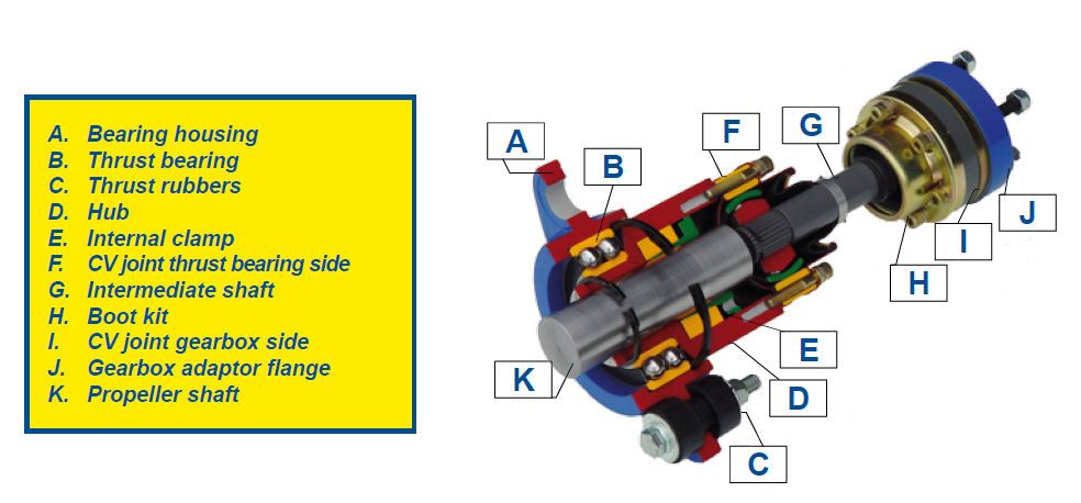
Got that? Yes, move on. No? Ok basically it works like this, The thrust from the propeller is transferred up the Propeller Shaft (part K) to the Thrust Bearing (part B). The Thrust Bearing is solidly mounted to the superstructure of the boat (framing) so that it can push the boat through the water. The output from the Transmission is transferred via the CV joints (part F & part I) and Intermediate Shaft (part G) to the Propeller Shaft (partK) via the Thrust Bearing (part B). Whew!
So, why all these extra parts? you ask. Well in a conventional boat the arrangement is for the propeller shaft to be hooked directly to the engine's gearbox. The thrust from the propeller is transferred to the transmission and its mounts or to the engine and its mounts. Alignment of the two mating flanges, propeller flange and transmission flange are critical, usually less than 2 or 3 thousandths of an inch.
 | ||
| Photo Credit: http://www.todddunnmicroyachts.com/tortuga/repower-2.html |
The setup above you can see the misalignment of the Propeller Shaft flange and the flange on the Transmission. This situation normally requires the adjustment of the engine or transmission mounts to get the two flanges to meet within tolerances. The process can be tedious. Depending on when/where the adjustments are made, in the water, out of the water etc. the alignment can fall out of tolerance. Alignment call also change due to transmission mount wear, engine mount wear, shaft cutlass bearing wear or grounding etc.
This is where the Python Drive (and there are others that work on the same/similar principals) come into play. A constant velocity joint allows a wide range (or narrow) of movement between the driving force (propeller shaft) and the prime mover (engine) or in the case of a car the drive shaft and the wheel. They work something like this.
In the case of the Python Drive the range of motion is much smaller than on a car, between 2 and 8 degs. Zero degs of alignment is not recommended as it will prevent the CV joints from self lubricating.

This angle allowance works in all orientations so it allows for a much higher degree of misallignment without possibly damaging the transmission or your engine and their mounts. There is also a fair amount of fore and aft to account for flexing of mounts in those directions. The Thrust Bearing (part B) is also soft mounted with rubber inserts to allow some degree of movement of the propeller shaft.
 |
| Photo Credit: http://www.cruisersforum.com/forums/f54/installing-a-3jh4e-yanmar-rant-36940-2.html |
Above you can see a typical Python Drive installation as described.
So, what's that all got to do with me wanting a custom Intermediate Shaft (part G)? you ask. Well, the company that makes the Python Drive is in The Netherlands (Holland). They no longer have a Canadian Distributor. I contacted them directly to get info on having a custom 1m (meter) shaft made for my model of Python Drive. The quote was reasonable:
Shaft: €55 - $80.00
Shipping: €80 - $116.25
Shipping: €80 - $116.25
Payment has to be made via direct bank transfer to their account in the NL. So off I go like a hurd of turtles to the bank this morning to get the money sent off by International Money Transfer. The teller hands me the quote:
Shaft: €55 - $80.00
Shipping: €80 - $116.25
Bank surcharge: $30.00
EMT: $100.00
Total: €224.51 - $326.25 Cdn
Shipping: €80 - $116.25
Bank surcharge: $30.00
EMT: $100.00
Total: €224.51 - $326.25 Cdn
After I picked my jaw up off the floor I had her tear that up and got out of there as quickly as I could. That's nuts! Over 4 times what the cost of the part is. So sent off a flurry of emails to the company, on hold, off hold, looking for a way to transfer the money etc. I spent about 2 hours online this afternoon looking at online services that could do the transfer to a company account. The first six were no go, they only did to individuals. On my last attempt before giving up I stumbled across an online service from the UK Xendpay that could do a direct deposit into the company's account. Their rates were reasonable. In the end all said and done it cost me:
Currency exchange: $186.52
Transfer Fee: $6.99
Payment Fee: $4.74
Delivery Fee: FREE
Total that you pay: $198.25 (Cdn)
Transfer Fee: $6.99
Payment Fee: $4.74
Delivery Fee: FREE
Total that you pay: $198.25 (Cdn)
So I'm happy. I saved a chunk of change ($128) that'll be better spent on some more boat stuff than paying for some Bank Manager's kids University PolySci or Underwater Basket Weaving text book. :-)
So, why do you need an custom 1m Intermediate Shaft (part G)? you ask. Well I guess I didn't explain that part. If you remember back earlier in the blog I told you about stretching the boat 1m in length. Well I need the engine to stay as far forward as possible near the Center of Gravity (CoG) as possible. If I wasn't able to get the custom shaft I was looking at having to have a custom Jack Shaft (shaft with two mating flanges) made locally (approx. $350) to span the gap between the transmission and the Thrust Bearing (part B).
Whew!
Thanks for looking in.
Feel free to carry on with your regular Interweb browsing activities.